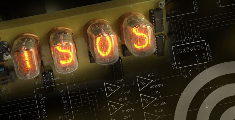
Nixie tube displays are best known from 1960s and 1970s measuring devices and electronic calculators. This how-to shows how to use these iconic tubes to build a clock with an integrated temperature display.
The project
Suitable for: Dedicated electronics hobbyists with Arduino knowledge
Costs: (including tubes, customs and shipping costs) approx. 100.-€
Time required:
- PCB assembly: 2 hours
- PCB production: 1 hour
- Software installation: 1 hour
What is required:
- the parts from this reichelt basket
- as well: 4 IN-12b display tubes, K155ID1 decimal decoder
Tools: soldering iron, screwdriver, side cutter, equipment for PCB production
Working with high voltages

The Nixie tube display technology requires an anode voltage of 170V DC to ignite the tubes. This is well outside the safe voltage specification – in other words, potentially lethal.
There is galvanic isolation from the 230V mains, but if you touch the high-voltage generator on the display and pick up two high-voltage points, you will feel this clearly.
Please take care when handling the printed circuit board. After the clock has been switched off, a voltage of over 60 V will remain on the components for about 2 minutes. The board should not be touched during this time. If you need to measure the display board, the old electrician’s rule applies: Put one hand on the object to be measured and the other hand in your trouser pocket! This prevents the current flowing through your body. So be careful when working on the displayboard.

How to get the time, date and temperature
The project was started because of the increasingly poor DCF reception: The large number of WLAN-enabled devices in the house and in the neighbourhood make the reception of the long-wave signal on 77.5 kHz increasingly susceptible to interference. So why not take one of the interferers and use its time information to control the clock? The result is a clock that displays the date and room temperature as well as the time.
The time and date can be obtained from any NTP server on the Internet. An ESP8266 module (WEMOS D1 Mini) connects to the Internet and controls the Nixie tubes at the same time. The temperature is measured by a DS18B20 sensor.


Power Supply for the Nixie Clock
The circuit description starts with the power supply: Since the Nixie tubes require a very high supply voltage of 170 V, a standard power supply cannot be used. A 12 V power supply with 300 mA is used as the power source. The 5V for the TTL logic is generated by a standard series regulator. A step-up converter converts the 12V from the power supply to 170V / 20mA for the Nixie tubes.
Caution! As before, be careful with the supply voltage. As the current is so low, there is no immediate danger to life. However, the 170V will make you feel the shock.
The step-up converter is a potential source of RF interference: it may happen that the WEMOS D1 Mini interferes with the square wave signals of the converter. For this reason, the converter on the display board and the WEMOS D1 Mini are placed on separate boards. Both boards are mounted on top of each other like a sandwich. The rectifier at the input of the power supply serves as reverse polarity protection, since the cables of the plug-in power supplies are not always connected in the same way.
Display board

I used the readily available IN-12b as the display tube. The TTL BCD to decimal decoder SN74141 is no longer available and is hard to find on Ebay. However, there is a Russian replacement, the K155ID1, which can also be found on Ebay.com. Be careful with the tube prices, as they do not include customs and import tax. However, if you are not afraid of direct imports from the East, you can also find the two components at German tube dealers.
Since the WEMOS D1 Mini has only a few output ports – 20 ports would be necessary – I decided to use serial control of the Nixie decoders. Three 74HC164 shift registers convert the serial information into parallel BCD information. A total of 24 bits are output for each write operation. Since the ARDUINO environment only supports 8-bit serial output, the software had to be adapted accordingly. Three ports were sufficient to control the display board, and the high voltage generation is also located on the display board. The anode voltage of 170V can be precisely adjusted using a multi-turn potentiometer.
The IN-12b must be mounted in a socket, never soldered directly. The original sockets for the IN-12b fit the PCB. Although they are not intended for PCB mounting, but for free wiring, they can be mounted on the PCB with adapted holes. I sawed off the tabs for fixing the sockets to keep the board from growing too much.

Processor board


Although the processor board is too big, it is exactly the same size as the display board, so both boards fit neatly on top of each other. I used the free space for an experimental panel, as there are still three free ports (1x analogue, 2x digital) that can be used as needed.
When I designed the circuit, I thought I could drive the shift registers directly with the WEMOS D1 mini. Unfortunately, the output level of the WLAN module was set too low, so the shift registers produced random results when controlled with the 3.3V of the WEMOS D1 mini. This problem was solved with a Schmitt trigger IC: The CD 40106 contains six Schmitt-trigger inverters which convert the signals into real TTL signals. Two of them are always connected in series to prevent the signals from being inverted when they reach the shift registers.
On the bottom of the board there are two LEDs, two buttons and the DS18B20 sensor. One of the buttons is a reset button and the second is used to switch the software to WLAN configuration mode. The configuration mode is indicated by an LED. The second LED indicates the successful registration of the clock in the WLAN.
The WEMOS board is equipped with a blue LED which cannot be switched off and which always flashes when data has been transferred to the shift registers. The LED can be easily removed from the board to avoid irritation.

Software
The software for the Nixie clock is completely programmed in the ARDUINO environment, even the libraries have been adopted. Because of their quality, it was necessary to pay attention to possible sources of errors during the software development and to document them with links. It was these links that made it possible for the clock to function correctly.
In order to avoid errors in the individual libraries, they had to be reprogrammed in such a way that a library that does not calculate the date had to be used to contact the NTP server, while another library that could not contact the NTP server had to be used to calculate the date.
Important to know: NTP servers do not provide absolute dates or times. They only show the number of seconds since 1 January 1970 – the so-called UNIX time (UTC). The correct date and time must still be calculated from this.
However, as UTC does not know daylight saving time, and leap years are also incorrectly calculated, these factors have to be taken into account by programming.
Another problem was the temperature sensor, whose library did not seem to tolerate the standard Do/While loop of the ARDUINO environment. This resulted in two zero readings and a complete system crash. The potential rebuilder is spared this experience, as in the course of this how-to all bugs were found and worked around, so that the software should now work with the libraries documented in the source code. The full version of this software is available as software:
Operating the Nixie clock
How do I start the Nixie Clock? In order for the clock to receive its UTC time, it must be connected to the Internet. This means it must be connected to a wireless router. To do this, the clock needs to know the SSID and password of the desired wireless network.
This requires an end device (PC, tablet or smartphone) that is already connected to the network: When the clock is switched on, press and hold the Config button to start the web server in the clock. If you open the Wi-Fi settings of the end device, you will find the same web server with its Wi-Fi access point.

When you select the clock, you will be asked for a password. This can be found in line (86) of the software’s source code: wifiManager.autoConnect(“Nixie-Uhr”, “Nixie-IN12b”);
First comes the Wi-Fi name of the clock, then the password. The password must be at least 8 characters long.
After entering the correct password and pressing the ‘Next’ button, the end device is paired with the clock. The default web browser of the end device is launched and a configuration page is displayed. However, no other browser must be open during this action, otherwise the configuration page cannot be displayed.

When you click ‘Configure WiFi’, the entire WiFi environment is scanned and any networks found are displayed.

Then select the network and save it by entering the password and clicking ‘Save’. The clock will then log on to the WLAN. If this operation was successful, the red WLAN LED will light up continuously. Do not be surprised if the clock’s web server stops: The previously active WLAN connection is restarted. This process can take up to a minute – only then will the first data be displayed on the clock.
The Nixie clock is now set up. Of course, if you don’t want to enjoy your timepiece without a case, you can still give it an attractive home.