


Test and measure your digital circuits with LabVIEW from NI and the portable USB logic analyzer and digital pattern generator from Digilent
As laboratory space becomes less and less and development teams are more and more dispersed, companies are opting for all-in-one equipment to complement traditional laboratories. This creates a need for mobile test and measurement stations that can support any type of development. USB test and measurement devices can be used in a wide range of applications, including testing embedded systems and maintenance of electronic devices. In addition, captured data can be quickly downloaded to a computer and conveniently shared with others. Users can also send data directly to the cloud and build automated test labs.
Digilent Inc, A National Instruments Company, is distinguished by its unique expertise in FPGA systems, test instruments and also software. Digilent’s boards are ready-to-use development platforms with a wide range of functions. Engineers around the world use Digilent’s USB test and measurement equipment to shorten design cycles and increase efficiency by keeping an oscilloscope, logic analyser, signal generator and more within easy reach. All Digilent solutions come with a powerful and comprehensive library of documentation, reference manuals, tutorials and other informative content, available free of charge to anyone who needs it.
The Digilent Digital Discovery is a combined logic analyser and pattern generator that allows you to debug, visualise and simulate signals in digital systems.
The free WaveForms software can be configured to work like any of the following instruments logic analyser, pattern generator, digital input/output device, digital bus analyser, programmable power supply. It is compatible with Windows, Mac, Linux and Raspberry Pi.
National Instruments LabVIEW provides a graphical programming approach that helps you visualize every aspect of your application. This includes hardware configuration, measurement data and debugging. These are the advantages of using LabVIEW:
- Program – supported by intuitive graphic programming – just as you think.
- Connect to almost any hardware with unparalleled hardware support.
- Collect and visualise data quickly.
- Work together with other software tools.
The following guide shows how the Digilent WaveForms VIs LabVIEW package can be used to test and measure digital circuits.

Requirements:
- A Digital Discovery USB logic analyser and pattern generator
- A computer with the latest version of WaveForms and LabVIEW Community.
Note: WaveForms can be downloaded from the WaveForms website. The installation process is described in the WaveForms Getting Started Guide. During the installation of WaveForms, the Digilent WaveForms Runtime is also installed, which is required by the WaveForms VIs.
Note: An NI account is required to download LabVIEW. LabVIEW Community can be downloaded from the LabVIEW Community website. A quick start guide is available here: LabVIEW Community Getting Started. When you install LabVIEW Community, the VI Package Manager and VIPM browser are installed. Both are used later in this tutorial.
Hardware Setup:
Connect the Digital Discovery to the computer using a USB cable.
Software setup:
Open the VI Package Manager (VIPM) browser.

Search for “Digilent”, open “Digilent WaveForms VIs” and click “Install.

Close the window after installation and start the VI Package Manager. Once it opens, search for Digilent WaveForms VIs and double-click on them.

Click on “Show Examples”.

The following example demonstrates the functions of the digital I/O device and how to use the digital I/O pins.
Digital e-input/output example – simple loopback
Download the provided example file digital_io_2.zip and unzip it. Double-click on it to open it with LabVIEW Community. You can use all instruments used in the example in your own VI. Play around and see what else you can develop.
To access the Digital Discovery digital I/O pins within LabVIEW, the following SubVIs are available in the Measurement I/O –> Digilent WF Vis –> Dig container:
- Initialize: Allows the user to select Digilent’s test and measurement device and sends the device handler to the other digital I/O SubVIs.
- Read: Used to view the status of a specific set of digital I/O lines.
- Write: Used to set the state of a specific set of digital I/O lines.
- Close: Closes the instrument when the program ends, making it available for another software (no instrument can be controlled by two programs at the same time).
- Also available are other SubVIs for adding tristate buffers to the input/output lines, resetting the instrument or retrieving the line states (high impedance / static). These are not used in the example.

A LabVIEW virtual instrument consists of two parts: the front panel and the block diagram.
The front panel contains all controls and displays for data input and output and serves as a user interface while the program is running.
The block diagram contains those blocks which are present on the front panel, but also other blocks which are necessary for processing the information and the connection between these blocks. A new block can be added to both windows by right-clicking on a free space in the respective window and then selecting the required block from a library. Existing blocks in a window can be modified by right-clicking on the block in question.
In the following the front panel and the block diagram of this example are presented.
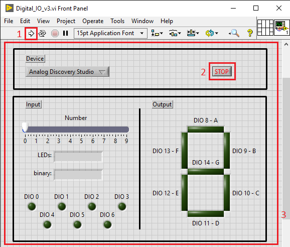
The front panel contains – besides the menu bar – the settings for the alignment, the “search” button, etc. (for more information, see: LabVIEW Community Getting Started), the “Run” button to run the program (1), and the panel itself (3). Control and display objects are placed in the control panel.
In the example, the panel is divided into two parts using design elements. The upper part contains a drop-down list with the name “Device”. This is used to select the test and measuring device used. The Stop button (2) is also located here. With this button the program can be stopped and all digital input/output lines are set to LOW.
The lower part contains a slider from 1 to 9 (control), two text fields (display), 7 virtual LEDs and a 7-segment display. When the programme is executed, the numbers of the slider determine which segments of the 7-segment display should light up, and the list of these segments is displayed in one of the text fields. The other text field contains the binary number to be written to the digital input/output lines 0 to 6. Virtual LEDs indicate the status of these lines. The 7-segment display is connected to the digital input/output lines 8 to 14, and the segments are switched on or off according to the status of these pins.
The block diagram contains – besides the menu bar – the settings for the alignment, the “Search” button, etc. (for more information, see: LabVIEW Community Getting Started), the “Run” button (the program can also be started from here) and the panel itself. Control, display and data processing blocks and structures are placed and connected in this panel.
In this example, the block diagram is divided into three parts using design elements and functional structures. The first part called “Device selection and initialization” contains the “Device” drop down list, compares its output with predefined strings and initializes the Digital I/O instrument with the selected device name. This part has no input signals, but two output signals: the Digital I/O Instrument’s device handler and the error signal.

The next section is executed in a while loop, i.e. it is repeated until a certain condition is met, with a waiting time of 100 ms between iterations. This part has as input signals the two output signals of the previous section. According to the number set on the slider, the two strings are determined, which are displayed on the front panel. The binary string is then converted into a binary array and this array is then sent to the digital input/output lines 0 to 6 and to the seven virtual LEDs which indicate the status of these lines.
The next step is to read the status of the digital input/output lines 8 to 14 and control the segments of the 7-segment display according to the values received. The loop is exited if an error occurs or the “Stop” button on the front panel is clicked. The handle of the instrument and the errors are sent to the next part.

If the loop is exited, the state of all virtual LEDs is set to “false” using the property nodes, the strings are replaced by an empty string and then a boolean array with lots of zeros is written to the digital input/output lines (thus setting all lines to LOW). The device is closed and is thus available for other programs. If errors have occurred, an error message is displayed.

To run the VI, first select the Digital Discovery as the used device in the front panel, then click the Run button.
Connect DIO pins 0 to 6 to DIO pins 8 to 14 as shown in the figure below. DIO lines 0 to 6 are used as the output and are controlled by the slider. Since the segments of the 7-segment display are connected to the digital input/output lines 8 to 14, the number set on the slider is displayed when the respective pins are connected. The program can be ended with the stop button on the front panel.


