Smart home systems have become more and more popular in recent years. But sometimes they can have limits when it comes to missing interfaces, expandability or adaptability. We’ll show you how to handle it yourself and build your own Raspberry Pi smart home centre, which you can customise and expand to your liking. Here’s how to get started.
The project
Suitable for: beginners with basic knowledge, advanced
Time required: about 1-2 hours
Budget: about £70
You need: 1x Raspberry Pi3 set, RPI relay board (network cable optional)
Can be extended with: any smart home system
You will also need: screen, PC keyboard, internet connection
Advantages compared to complete smart home systems
In this how-to, we’d like to introduce you to openHABian, a free piece of software which is a Debian derivative that turns your Raspberry Pi into a smart home server. But why should you do this if, for example, you already have an Amazon Echo System or Google’s Smart Home?
The special thing about openHABian is that you can integrate all your existing Smart Home systems (list of supported systems here), so you only need one central control unit. You can also create interfaces with devices that do not have a smart interface by default.
Install openHABian on the Raspberry Pi
Step 1: Prepare microSD card
First, set up your Raspberry Pi as an openHABian server. To do this, download the image from the openHAB website, unzip it and flash it with suitable software, such as Etcher, onto a microSD card.
Step 2: Make an internet connection
Since an active internet connection is required during installation, either enter the SSID and password of your WiFi network in openhabian.conf or connect your Raspberry Pi to your router via a network cable. We recommend the second option, as connecting with WiFi can often cause problems during installation.
wifi_ssid = “My Wi-Fi SSID”
wifi_psk = “password123”
Step 3: The installation
Now plug the microSD card into the Raspberry Pi and connect it to the power supply. The installation starts automatically and takes about 25 minutes, depending on the version of your Raspberry Pis (Rpi) and your internet connection.
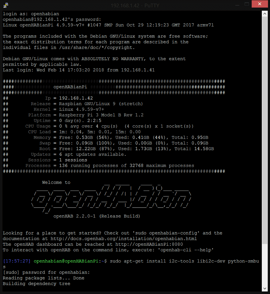
If the installation was successful, you will be asked for username and password (openhabian / openhabian). Then you will see an openHABian lettering as an ASCII graphic.
Step 4: Define IP address
Determine the IP address of the RPis by typing ‘hostname -I’ in the console. Now enter this in your browser and you will see the control panel of your openHAB server (you can select ‘Standard’ here).
Finally, we recommend assigning a static IP address to the Raspberry Pi. You can do this in the settings of your router. Furthermore, a samba connection, as well as external access to the Raspberry PI via SSH during setup, are very helpful. Both services are preconfigured and can be reached at the IP address with the default username and password.
Your first smart home application
With the very first smart home application for Raspberry Pi, we want to be able to do something that is impossible with any other conventional smart home system. We want to use a new interface to switch a relay that allows you to control devices in your house that do not have a smart interface, such as your garage door, exterior and interior lighting, air conditioning, electric door locks, shutters … and many more.
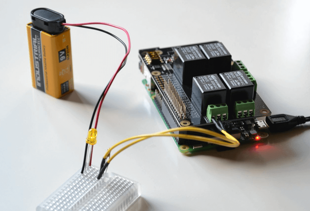
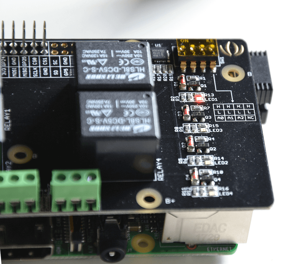
Step 1: The hardware
Plug the relay board into the Raspberry Pi as shown and connect the circuit to be controlled (35V max!) to relay 1. This is all you need for hardware installation.

Step 2: Insert your code
Next, copy the following scripts to the corresponding folders in the conf folder of your Raspberry Pis (the script is Python script). Use the samba connection to your RPi.exec.things:
Thing exec:command:remote-send [
command=”sudo python3 /etc/openhab2/scripts/relaySwitch.py %2$s”,
interval=0,
autorun=true]
]
Relay_Switch.items:
Switch Relay_Switch_1 <poweroutlet>
Switch Remote_Send { channel=”exec:command:remote-send:run” }
String Remote_Send_Args { channel=”exec:command:remote-send:input” }
String Remote_Send_Out { channel=”exec:command:remote-send:output” }
Relay_Switch_1.rules:
rule “Relay Switch 1”
when
Item Relay_Switch_1 received command
then
while(Remote_Send.state == ON){
Thread::sleep(500)
}
if(receivedCommand == ON){
Remote_Send_Args.sendCommand(“1 ON”)
}else{
Remote_Send_Args.sendCommand(“1 OFF”)
}
while(Remote_Send.state != OFF){
Thread::sleep(500)
}
logInfo(“Relay_Switch_1”, “Result:” + Remote_Send_Out.state )
end
relaySwitch.py:
#!/usr/bin/python3
import argparse
import smbus
class Relays():
def __init__(self):
self.dev_addr = 0x20
self.dev_reg_mode1 = 0x06
self.dev_reg_data = 0xff
self.bus = smbus.SMBus(1)
self.block = self.bus.read_byte_data(self.dev_addr, self.dev_reg_mode1)
def set_on(self, relays):
print(“Setting {} on…”.format(relays))
self.block &= ~(0x1 << relays)
self.bus.write_byte_data(self.dev_addr, self.dev_reg_mode1, self.block)
def set_off(self, relays):
print(“Setting {} off…”.format(relays))
self.block |= (0x1 << relays)
self.bus.write_byte_data(self.dev_addr, self.dev_reg_mode1, self.block)
def read_bytes(self,relays):
self.dev_reg_data |= (0x1 << relays)
block = self.bus.read_byte_data(self.dev_addr, self.dev_reg_mode1)
if __name__ == “__main__”:
def state2bool(state):
if state.lower() == “on”:
return True
elif state.lower() == “off”:
return False
else:
raise argparse.ArgumentTypeError(“State can either be on or off”)
parser = argparse.ArgumentParser(
description=”Change the state of a relays”
)
parser.add_argument(“relay_id”, type=int)
parser.add_argument(“state”, type=str)
args = parser.parse_args()
relays = Relays()
if state2bool(args.state):
relays.set_on(args.relay_id-1)
else:
relays.set_off(args.relay_id-1)
Step 3: Activate the circuit of the relay
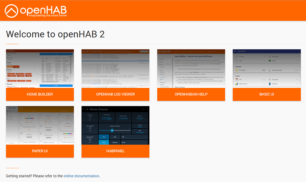
Next, you need to create the button that will be used to switch the relay in the user interface and install various bindings. To do this, enter the IP address of your RPis in the address field of your browser and navigate as follows: PAPER UI-> Addons-> Bindings.
Search for GPIO Binding and click “Install.” The same is done with the EXEC Binding and the REGEX Transformation.
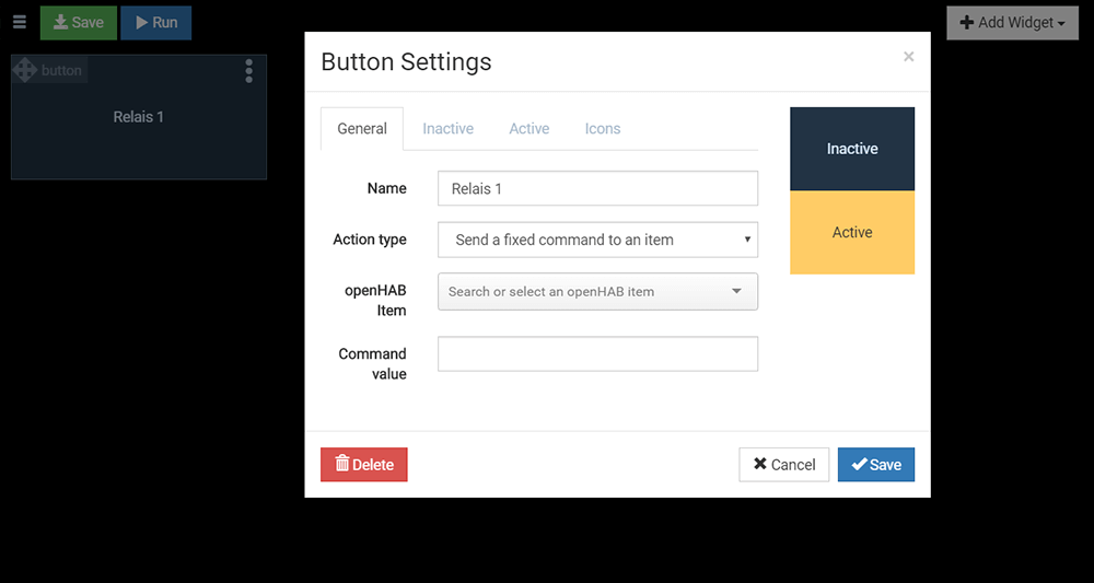
Then navigate back and select HABPANEL. Create a new switch here and under HABItem, select the relay item “Switch_Relay_1” to be controlled.
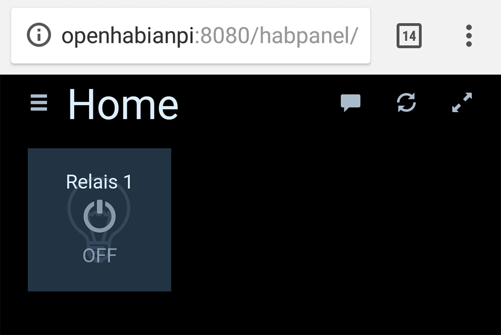
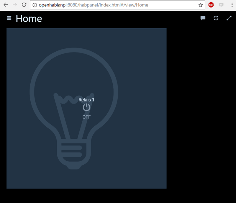
Save and click ‘Run‘. If you now operate the switch, you should hear the click of the relay, the corresponding LED should light up and your connected circuit should be activated.
Step 4: Find errors
If nothing happens, check if the i2c protocol is set up correctly (follow these steps) or check if you have granted enough rights (please follow these steps). The openHAB Log Viewer is useful for debugging and can be found under Port 9001.
Access outside of your own network
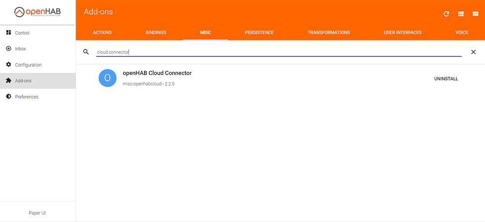
Of course, you will want to not only have control over your equipment in-house, but from anywhere. To enable this, openHABian provides a cloud-based service. First, add the openHAB Cloud Connector in the HABPANEL under MISC. Then register yourself and your openHAB server at myopenhab.org. You can find the required UUID y entering the following in the console of your RPis:
UUID: cat /var/lib/openhab2/uuid
Secret: cat /var/lib/openhab2/openhabcloud/secret
After logging in, the link to your control panel will be displayed directly on the start page. Like an app, you can now link it to the start screen on your smartphone. So, you always have full control over the functions of your home.